Crossing the 10-Transistor Barrier of TCAD Device Simulation
[update] New development on this front can be found in this article.
It is traditionally believed that TCAD device simulator is only useful for simulating one or two transistors.
In recent years, TCAD has been used to simulate small circuits, such as SRAM with 6 MOSFETs. However, the traditional prejudice against TCAD simulators is still largely valid. Simulating a circuit beyond 10 transistors, with 20,000 or more mesh nodes seems impractical due to the excessively simulation time and hardware requirement.
In this article, we shall present the latest developments at Cogenda. Cogenda offers the world's first TCAD solution that overcomes the 10-transistor barrier, and brings TCAD simulation to a new era.
Why is Simulating Larger Circuits Difficult?
While modern TCAD simulators do not have a hard limit on the number of mesh nodes (hence the number of transistors), simulating 10 or more transistors is not only extremely expensive in terms of simulation time and hardware cost, but also is prone to convergence problems.
Scaling Up and Cost of Simulation
As the number of transistors in the circuit grows, as shown in Fig. 1, the number of mesh nodes in the TCAD model increases. Both time and memory space required in TCAD simulation increases as the problem size scales up.

Fig-1 Memory requirement for simulating CMOS circuits with Cogenda's Genius device simulator.
The most expensive computation step in TCAD simulation is the solving of linear equations. In terms of memory requirement, direct linear solver requires 5-10 times more memory space than iterative solvers for larger circuits, and has worse scaling trend.
In terms of computation time, direct solvers have time cost of asymptotically O(n2), where n is the number of mesh nodes. On the other hand, the time cost of iterative solvers scales as O(kn), where k is the number of iterations needed. This makes iterative solvers advantageous for "easy" problems, which converges in a few steps. However, for difficult problems, too many iterations are needed, and iterative solvers could be even slower than the direct solvers. For the most difficult problems, iterative solvers may fail to converge at all.
Convergence Difficulties
As one goes beyond the simplest circuits, floating nodes or floating regions, the voltages of which are determined by the delicate balance of two or more very weak current paths, appear in the circuit. For example, the latch circuit shown in Fig. 2 will always have two floating nodes (dnp/dnn or n3p/n3n).
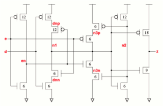

Fig-2 Circuit diagram and mask layout of a latch circuit.
Floating regions are well-known to cause convergence difficulties in TCAD simulation. Technically, floating regions detriment the performance of both linear solver and non-linear (Newton) solver. Firstly, systems with floating regions leads to Jacobian matrices with huge condition number up to 1020. Iterative linear solvers are almost certain to fail in these cases, even some high-performance direct solvers may die in some extreme cases. Secondly, the non-linear solver will often encounter local minima and almost-flat "valleys", and often fail to reach the specified convergence criteria.
Traditionally, TCAD users resort to transient-mode analysis for better convergence. One keeps the voltage sources constant and let the device settle to its steady-state. However, this typically requires a large number of time steps.
As one is forced to use the expensive direct linear solvers and the slow transient-mode analysis, the simulation time and hardware requirement quickly becomes intolerable as mesh nodes exceeds 100,000. These practical constraints limited TCAD users to the simplest circuits, hence the 10 transistor barrier.
Cogenda's Solution
Cogenda offers a unique "pseudo-time" algorithm that solves the scaling and convergence problems of TCAD. Figure 3 shows a CMOS latch circuit with 14 transistors and nearly 300,000 mesh nodes, which is unprecedented for TCAD device simulators. Cogenda's Genius device simulator is able to handle this and even larger structures smoothly.
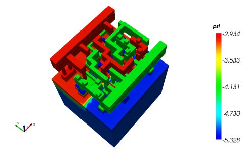
Fig-3 Simulated electrostatic potential profile in the latch circuit.
The pseudo-time algorithm is a transient-mode method, and shares the same good convergence properties of transient analyses. On the other hand, instead of using the physical time, it uses pseudo time steps that optimally drives the device to its steady-state.
Figure 4 illustrates how the pseudo time performs compared to standard steady-state algorithms. The classical algorithm (used in all TCAD software) has convergence issues, and requires direct linear solvers (high memory consumption) and is rather slow. An early implementation of the pseudo time algorithm converges well with iterative linear solvers, saving memory space, and is faster. In the recent 1.7.2-3 release of Genius, an optimized pseudo-time algorithm has been included, which further reduces the simulation time.


Fig-4 Memory and time requirements (simulating a 6T SRAM device on an 8-core workstation)
Although the pseudo-time method contributed a major performance boost to the Genius simulator, it is by no means the single technology behind Cogenda's highly efficient and scalable products. Each component of Genius has to be designed and optimized for parallelism. Any bottle-neck, even one in a less important module, would ruin the overall performance.
Conclusion
Through extensive research and development over the past years, Cogenda has successfully crossed the 10-transistor barrier for TCAD device simulation. Simulating circuits with over 20 transistors and 600,000 mesh nodes has become practical with cheap hardware and moderate time.
-
WebTCAD

WebTCAD is the web version of Cogenda's VisualTCAD, a powerful tool of TCAD process and device simulation. It's mainly designed for teaching purpose, aimed at demonstrating/simulating industry-standard semiconductor fabricating and working process. The intuitive graphic UI, step-by-step workflow, and fully featured post process ability make it much easier for university teachers and students to use.
-
What's New
- VisualTCAD 2024.10 released [2024-11-04]
- VisualTCAD 2024.06 released [2024-07-18]
- VisualTCAD 2024.03 released [2024-04-09]
- VisualTCAD 2024.02 released [2024-03-05]
- VisualTCAD 2023.12 released [2024-01-17]
- VisualTCAD 2023.11 released [2023-12-07]
- MozzTCAD 2023.10 released [2023-11-06]
- VisualTCAD 2.2 3D device simulator Genius support stress induced multi-valley mobility model for Si and SiGe material. [2022-11-01]
- VisualTCAD 2.1-p4 Simulation speed of 3D device simulator Genius increased by 10%~30%. [2022-08-24]
- VisualTCAD 2.1 3D device simulator Genius support nanometer device such as FDSOI and FinFET. [2022-05-15]
- VisualTCAD 2.0 First release of 2D process simulator Genes after years of development. [2021-10-17]
- Vspice 2.2 released [2019-4-15]
- Vspice 2.0 released [2018-10-20]
- VisualTCAD 1.9.2-3 Comes with revamped Total-Ionizing Dose effect simulation and supports SEE simulation in FDSOI circuits. [2017-10-15]
- Cogenda partners with POLYTEDA to distribute PowerDRC/LVS in Asia. [2017-9-15]
- Vspice 1.0 released [2017-4-15]
- CRad's FREE on-line version ForeCAST is open to you now! [2015-12-15]
- VisualTCAD 1.8.2-6 Comes with Total-Ionizing Dose effect simulation, among other improvements. [2015-7-10]
- Cogenda presented a quantitative analysis on the SEU rate of radiation-hardened SRAM cell due to elastic collisions at NSREC 2014. [2014-7-28]
- VisualTCAD 1.8.0-1 released with a new product for space radiation environment and effects analysis [2014-3-22]
- Cogenda presented a fully-physical simulation framework for single-event effects in semiconductor devices at RADECS 2012 [2012-9-28]
- Cogenda to present the super large TCAD device simulation at SISPAD 2012 [2012-6-18]
- Technical: Half-implicit solver for million-mesh-node TCAD device/circuit simulation [2012-6-18]
- VisualTCAD 1.7.4 released [2012-6-3]
- VisualTCAD 1.7.3 released [2012-1-1]
- VisualTCAD 1.7.2-5 released [2011-09-29]
- Cogenda to present MOSFET inverse-modeling technology at SISPAD 2011 and the companion workshop. [2011-07-17]
- Technical: Crossing the 10-transistor barrier of device simulation. [2011-07-12]
- New product: VisualParticle/GSeat for radiation effect analysis. [2011-07-01]
-
Solar Cell with Surface Texturing
A section (300x300 um) of a solar cell with inverted pyramid surface texturing, with over 600,000 mesh nodes.


Anti-reflection coating present at the front surface is taken into account in the simulation.